

Introduction
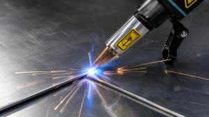
Adding filler wire changes handheld laser welding more than many first-time users expect. In autogenous welding, the laser only has to melt and join the existing joint edges. Once wire is added, the same process also has to melt a continuous stream of filler and place that metal into the weld pool while the gun keeps moving. That puts wire feed speed, laser power, and travel speed into the same balance. Too much wire for the available heat can leave filler sitting high on the joint. Too much heat or too little travel speed can burn through thin sheet. The goal is not to find a universal power-to-wire ratio; there is no single ratio that works across different materials, wire diameters, joint types, and machines. The goal is a stable transfer that adds only the filler the joint needs while preserving sound fusion.
Why wire feed, power, and travel speed have to be tuned together
Each setting controls a different part of the same process. Laser power provides the energy available to melt the joint and the filler. Travel speed controls how long the beam acts on each section of the seam. Wire feed speed controls how quickly filler enters the process. Change one and the balance shifts. Slow the gun down without changing wire feed and more filler is delivered into each inch of weld. Speed up without changing wire feed and the amount of filler per inch drops.
Research on filler-wire laser welding supports that relationship. A 2021 study of wire melting and transfer found that both wire feed rate and the relative position of the wire to the laser strongly affected transfer stability. An earlier optimization study found that welding speed, wire feed rate, and laser power all influenced bead geometry. The equipment and materials in those studies differ from handheld systems, so the exact values are not transferable. The useful point is the interaction: these settings need to be developed as a set.
Think about filler per unit length, not wire speed by itself
A simple shop-floor way to understand the relationship is to compare wire speed with travel speed. If wire feed stays constant and travel speed doubles, roughly half as much wire length is delivered per inch of seam. Slow travel by half and roughly twice as much wire length reaches that same inch. Wire diameter matters too: a 1.6 mm wire carries substantially more metal than a 1.0 mm wire at the same linear feed speed. This is one reason copying a wire-feed number from another setup can produce a completely different bead.
What too much or too little wire looks like
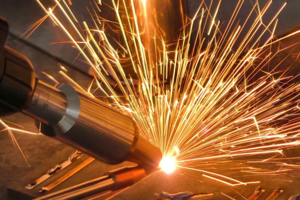
When wire feed is too high for the available heat and travel speed, the filler may stack up, form a high convex bead, push against the joint, or transfer in irregular lumps. When feed is too low, the base metal may still fuse but the joint can end up underfilled or too small for the intended bead profile. Those symptoms are useful clues, but wire speed is not the only possible cause.
Denaliweld’s published parameter table shows why there is no single “correct” feed setting. Many carbon-steel and stainless starting recipes use roughly 8-10 mm/s, but the recommended value changes with thickness, wire diameter, power, and whether single or dual wire is used. Some manufacturers also provides an adjustable wire-feed range rather than one fixed speed. Treat manufacturer values as starting points for the actual system, not universal targets.
Wire position can matter as much as wire speed
A good feed rate will still look bad if the wire misses the right part of the weld pool. The filler needs to enter a region where it can melt and transfer smoothly. If it lands too far ahead of the pool, too far behind it, or outside the effective energy zone, it may ball up or ride on top of the joint. Before making a large power change, check the wire nozzle, feed angle, tip position, working distance, and whether the wire actually tracks the seam. In the 2021 study, the relative distance between the wire and laser was one of the variables most strongly tied to transfer stability.
What laser power can - and cannot - fix
More power gives the process more melting capacity, but it is not the first answer to every wire-feed problem. If filler is being delivered too quickly or aimed at the wrong place, increasing power can simply make the joint hotter while the transfer remains unstable. On thin material, that can turn a manageable setup problem into burn-through or excess heat input.
Look at the base metal first. If the joint is fusing properly but filler remains high on top, verify wire position and trim the feed rate before adding power. If the base metal itself is not fusing and the wire is also failing to melt cleanly, then a controlled power increase or a modest reduction in travel speed may be appropriate. Work inside the machine manufacturer’s tested range and verify the weld after each change.
More power and slower travel are not the same adjustment
Both can increase heat delivered to a section of the joint, but they change the process differently. Slowing down also increases the amount of filler delivered per inch unless the wire speed is reduced at the same time. That is why a weld can become larger and more convex after the operator slows down to gain penetration: the joint is receiving more heat and more filler per unit length. If travel speed changes, the wire balance needs to be checked again.

Why travel speed is often the hidden variable
On a handheld system, travel speed is the setting most likely to change without anyone touching the screen. A slow section of the weld receives more energy per unit length and, with a constant wire feed, more filler per unit length. A fast section receives less of both. The result can be a bead that changes from wide and high to narrow and underfilled even though every machine setting stayed the same.
This is also why a recipe that works for one operator may look different for another. Hand speed, gun angle, working distance, and line of travel all affect how the set parameters reach the joint. Machine data is useful, but operator technique still has to be repeatable.
How to make handheld travel speed more repeatable
During process development, mark a known coupon length and time the pass. That gives you an approximate travel speed instead of relying on feel. Use the same direction, stance, gun angle, and working distance on each test. Once the weld is stable, record the machine settings and the approximate travel speed together. That makes training easier and gives you something concrete to compare when a previously good recipe starts to drift.
A practical tuning sequence for filler-wire laser welding
Start with the part, not the knobs. Clean the joint, control the gap, clamp the coupon, confirm shielding gas, inspect the protective lens, and make sure the wire nozzle delivers the filler consistently to the intended point. Choose a wire diameter that makes sense for the joint. Wire feeding can help with bead size and limited fit-up variation, but it is not a substitute for unstable parts or an uncontrolled gap.
Next, load the closest machine-specific starting recipe. Denaliweld’s Welding Parameter Setting gives starting combinations for material, thickness, wire size, power, wobble, gas flow, and wire speed. Keep as many variables fixed as possible during the first comparison and run a short coupon at a steady travel speed.
If the base joint is already melting but filler is piling up, check wire aim and reduce wire feed slightly before reaching for more power. If the filler melts but the joint lacks fusion, verify focus and fit-up, then consider more power or slightly slower travel. If thin material is burning through, reduce heat input by lowering power or increasing travel speed, and then recheck wire feed because the filler-per-inch balance has changed.
Make one primary change per test. A reliable sequence is: confirm fit-up and wire position, establish stable fusion, set a wire speed that melts cleanly, then add only as much filler as the joint needs. Fine-tune travel speed after the transfer is stable. Keep a short record of each coupon. Changing power, wire feed, wobble, and travel all at once may eventually produce a decent bead, but it will not tell you which change fixed the problem or how to recover the process later.
A quick troubleshooting pattern
Wire piling high on the joint: check wire aim first, then reduce feed in small steps. Wire melts but the joint lacks fusion: confirm focus, fit-up, and travel speed before adding power. Burn-through on thin sheet: reduce heat input or move faster, then rebalance wire feed. Bead size changes along the seam: check operator travel consistency before rewriting the recipe. Sudden deterioration after a previously stable weld: inspect the lens, nozzle, gas flow, wire path, and working distance before assuming the parameters are wrong.
Use parameter charts as a baseline, not a guarantee
A published parameter chart is a good place to start, but the real part still has to prove the recipe. Material grade, joint design, gap, wire size, focus, shielding gas, torch angle, surface condition, and operator travel can all change the result. The same settings can produce different welds when any of those conditions move.
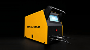
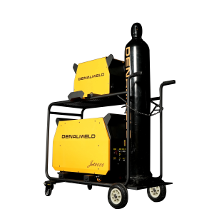
For Denaliweld equipment, record the actual part, material, wire size, power, wobble, gas flow, wire feed, approximate travel speed, and inspection result when a test works. A simple process record turns a successful coupon into a repeatable setup and gives the next operator a much better starting point than memory alone.
Conclusion
Wire feed, laser power, and travel speed work as one system. Power provides melting capacity, travel speed sets exposure time, and wire feed determines how much filler enters the joint. Start from a machine-specific recipe, make sure the wire is aimed correctly, keep travel speed repeatable, and change one variable at a time. Most importantly, verify fusion instead of judging the weld only by how smooth the top bead looks. For Denaliweld starting values, use the Welding Parameter Setting. If the application falls outside the published examples, contact DenaliWeld for project-specific guidance.
FAQs
What happens if wire feed speed is too high in laser welding?
Too much wire for the available heat and travel speed can cause filler to pile up, form a high convex bead, transfer unevenly, or fail to blend fully into the joint. Check wire position as well, because poor aim can create similar symptoms.
Should I increase laser power when I increase wire feed?
Not automatically. More filler needs enough energy to melt, but increasing power can create burn-through or excess heat on thin material. Increase wire in small steps and add power only when the weld shows that more melting capacity is actually needed.
How do I balance wire feed speed and travel speed?
Think about filler delivered per unit length of weld. Faster travel reduces filler per inch when wire speed stays constant; slower travel increases it. Keep travel repeatable while tuning wire feed, then recheck both if production speed changes.
Why does filler wire sit on top of the weld instead of flowing?
Common causes include too much wire, poor wire alignment, insufficient heat where the wire enters the pool, excessive travel speed, incorrect focus, or unstable fit-up. Check the wire path and setup before making a large power change.
What parameter should I adjust first when adding a wire feeder?
Start from a tested recipe and verify the setup first: fit-up, wire size, wire position, focus, shielding gas, and travel consistency. Once the base process is stable, tune wire feed in small steps and only change power or travel when the weld shows a clear need.